Content
- Introduction to the topic
- Hardware Requirements
- Software Requirements
- Environmental specifications and physical data
- NMEA 2000® network connection
- Power Supply
- NMEA 2000® network parameters
- Configuration
- Supported NMEA 2000® PGNs
- Supported J1939 PGNs
- PGNs in detail
- Error messages
- Software Update
- Setting Parameters
- Setting Instances
- Multifunction Displays (MFDs)
Introduction to the topic
The »Communication Interface Electric Drive – NMEA 2000®« is a gateway for integrating Fischer Panda electric drive systems with an NMEA 2000® network. The Interface works with EasyBox-equipped electric drive systems and converts CAN messages of the EasyBox to NMEA 2000® messages. So you can monitor your Fischer Panda electric drive system with NMEA 2000® displays. The »Communication Interface Electric Drive – NMEA 2000®« is certified by NMEA 2000® (https://www.nmea.org).
Hardware Requirements
- »Communication Interface Electric Drive – NMEA 2000®«
Software Requirements
- »Communication Interface Electric Drive – NMEA 2000®«: Release 1V10
Environmental specifications and physical data
| Storage temperature | -30 °C to +60 °C |
| Operating temperature | -20 °C to +50 °C |
| Operation type | nonstop |
| Mounting position | any |
| Supply voltage | 12 V or 24 V, Automotive (12–13,5 V or 24–28 V) |
| Nominal current consumption | < 32 mA @ 12 V < 17 mA @ 24 V |
| Housing | ABS Plastic |
| Protection class | IP30 |
| Overall dimensions | 151 x 80 x 60 mm (L x B x H) |
| Weight | 0,25 kg |
| FP item number | 0034130 |
| Circuit board | FP1409V5 |
NMEA 2000® network connection
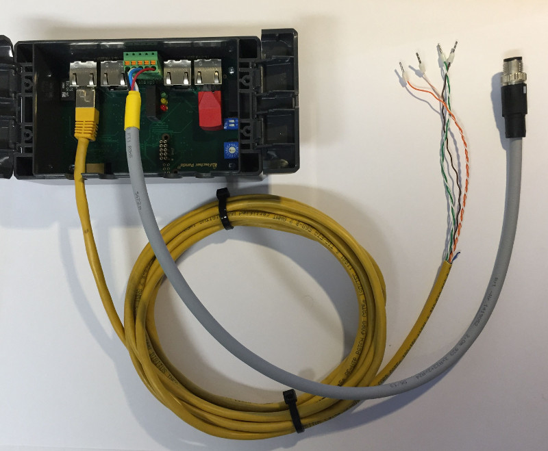
Connecting the NMEA 2000® interface with the EasyBox
The »Communication Interface Electric Drive – NMEA 2000®« is connected to the CAN bus of the SAC / GD2 *) using a patch cable with RJ45 connector on one end.
The RJ45 must be connected to the port »FP CAN BUS 1« of the »Communication Interface Electric Drive – NMEA 2000®«.
The lines of the open end must be connected to the terminals in the EasyBox.
*) SAC is an AC Drive Controller, GD2 is a display, control and battery monitoring unit.
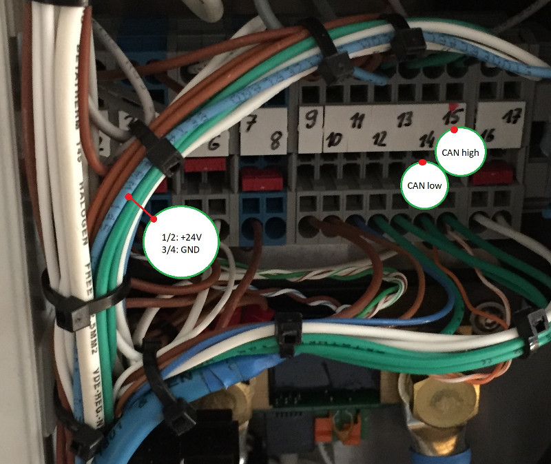
Terminal assignment of the EasyBox 48 V
| Terminal | Wire color | Assignment |
| 1 / 2 | brown | 24 V |
| 3 / 4 | green and white/green | GND |
| 14 | orange | CAN-Low |
| 15 | white/orange | CAN-High |
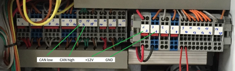
Terminal assignment of the EasyBox HV
| Terminal | Wire color | Assignment |
| 1 / 2 | brown | 12 V |
| 3 / 4 | green and white/green | GND |
| 15 | orange | CAN-Low |
| 16 | white/orange | CAN-High |
Connecting the Interface to the NMEA 2000® network
The connection to the NMEA 2000® network is established via the Adapter Cable fpCAN/NMEA 2000® (Fischer Panda article number 0024737).

The electrical interface for the NMEA 2000® network (USER CAN BUS) is labelled directly on the printed circuit board.
Pin assignment of »USER CAN BUS«
5-pin Phoenix Contact socket:
| Pin | Line | Label |
| 1 | Power source common | NET_C |
| 2 | CAN High signal line | NET-H |
| 3 | CAN Low signal line | NET-L |
| 4 | Shield | SHIELD |
| 5 | Power source positive | NET-S |
5-pin male NMEA 2000® connector (M12):
| Pin | Line | Color |
| 1 | Shield | — |
| 2 | NET-S | Power source positive | Red |
| 3 | NET-C | Power source common | Black |
| 4 | NET-H | CAN High signal line | White |
| 5 | NET-L | CAN Low signal line | Blue |

Power Supply
The »Communication Interface Electric Drive – NMEA 2000®« can be supplied with voltage via the NMEA 2000® network as well as via the EasyBox.
Fischer Panda recommends the power supply via the NMEA 2000® network. One advantage is that when the NMEA 2000® multifunction display is switched on, the »Communication Interface Electric Drive – NMEA 2000®« is also switched on.
| NOTICE |
| Property damage to the Hardware because of different supply voltages. If the Communication Interface is supplied with voltage via the NMEA network and the EasyBox at the same time, the hardware can be damaged. ► Make sure that the interface is supplied with voltage either via the NMEA network or via the EasyBox. |
 To ensure safe operation of the »Communication Interface Electric Drive – NMEA 2000®«, the supply voltage should not drop below 11 V. |
NMEA 2000® network parameters
| Manufacturer Code Fischer Panda GmbH | 785 (0x311 hexadecimal) |
| Product Code | 21023 (0x521F hexadecimal) |
| Class Code | 50 – Propulsion |
| Function Code | 155 – Motor |
Configuration
Start Addresses
| Input | fixed addresses 0x66, 0x67 (due to GD2 panel) |
| Output | Default address: Position of the rotary coding switch * 16 for CAN1 (NMEA 2000®) If the position of the rotary coding switch is “0” the default address is CAN_OUTPUT_ADDRESS = “128” |
Functions of the DIP switch
Switching Unit 1 (SW1):
| Position | Function |
| off | 125 kBaud on input (SAC / GD2) |
| on | 250 kBaud on input (SAC / GD2) |
Switching Unit 2 (SW2):
Switch 2 must always be in position »off« (0).
| Position | Function |
| off (0) | default |
| on | internal demo mode |
Supported NMEA 2000® PGNs
| ISO Acknowledgement | 059392 |
| ISO Request | 059904 |
| ISO Transport Protocol, Data Transfer | 060160 |
| ISO Transport Protocol, Conn. Management | 060416 |
| ISO Address Claim | 060928 |
| ISO Commanded Address | 065240 |
| ISO Software Version | 065242 |
| NMEA Request / Command / Acknowledge | 126208 |
| PGN List (Transmit and Receive) | 126464 |
| Heartbeat | 126993 |
| Product Information | 126996 |
| Configuration Information | 126998 |
| Engine Parameters, Rapid Update | 127488 |
| Engine Parameters, Dynamik | 127489 |
| DC Voltage / Current | 127551 |
Supported J1939 PGNs
| EEC1, Electronic Engine Controller | 61444 |
PGNs in detail
PGN 127488 – Engine Parameters, Rapid Update
| Engine Speed | available, is sent |
| Engine Boost Pressure | not available (0xFFFF) |
| Engine Tilt/Trim | not available (0xFF) |
PGN 127489 – Engine Parameters, Dynamic
| Engine Oil Pressure | not available (0xFFFF) |
| Engine Oil Temperature | Controller Temperature (SAC) |
| Engine Temperature | Drive Temperature |
| Alternator Potential | not available (0xFFFF) |
| Fuel Rate | not available (0xFFFF) |
| Total Engine Hours | not available (0xFFFFFFFF) |
| Engine Coolant Pressure | not available (0xFFFF) |
| Fuel Pressure | not available (0xFFFF) |
| Engine Discrete Status 1 | available, is sent |
| Engine Discrete Status 2 | available, is sent |
| Percent Engine Load | is calculated if the drive type is known |
| Percent Engine Torque | is calculated if the drive type is known |
PGN 127751, DC Voltage / Current
| DC Voltage | Battery Voltage measured by the SAC |
| DC Current | averaged DC Input Current of the SAC |
 The Voltage and especially the current may differ a little bit from the values shown by the GD2 display. This is because they are measured only by the SAC, whereas the GD2 display mesures via an external shunt over the whole system. |
PGN 61444, EEC1, Electronic Engine Controller
| Engine Load | is calculated if the drive type is known |
| Engine Speed | available, is sent |
Error messages
For a detailed description of the SAC Error Codes use the »User’s Manual for the AC Drive Controllers Family SAC«.
A detailed documentation of the NMEA 2000® »Engine Discrete Warning Status«, which is contained in PGN 127489, can be found in the original documentation that has to be bought from the NMEA website.
Since the »Engine Discrete Warning Status« of the NMEA 2000® PGN 127489 is defined for combustion engines, not all codes can be directly transferred to the SAC Error Codes, so the most similar ones are used. |
| SAC Error Code / Message | NMEA 2000® Error Message |
| (1) OVER CURRENT | Low System Voltage |
| (2) OVER VOLTAGE | Low System Voltage |
| (3) UNDER VOLTAGE | Low System Voltage |
| (4) BATTERY VOLTAGE LOW AT START | Low System Voltage |
| (5) POTENTIOMETER ERROR DURING OPERATION (THROTTLE_FAIL) | NMEA2000_ENGINE_THROTTLE_FAIL |
| (6) POTENTIOMETER NOT ZERO AT START (THROTTLE_POS) | Throttle Position Sensor |
| (7) OVER TEMPERATURE | Engine Emergency Stop Mode, Engine Shutting Down |
| (8) UNDER TEMPERATURE | Engine Emergency Stop Mode, Engine Shutting Down |
| (9) TEMPERATURE SENSOR ERROR (TEMP_FAIL) | Engine Emergency Stop Mode, Engine Shutting Down |
| (21) MOTOR OVER TEMPERATURE (DRIVE_TEMP) | Engine Emergency Stop Mode, Engine Shutting Down |
| (22) MOTOR TEMPERATURE SENSOR ERROR (DRIVE_TEMP_FAIL) | Engine Emergency Stop Mode, Engine Shutting Down |
| NMEA2000_ENGINE_TEMP | Engine Emergency Stop Mode, Engine Shutting Down |
The SAC indicates whether the main relay is closed. In this case the SAC is active. If the SAC’s main relay is open, Engine Shutting Down is set on NMEA 2000®. |
Error Messages on the Lowrance HDS 7 MFD
How does the Lowrance HDS 7 MFD evaluate the NMEA 2000® Error Messages?
The Lowrance HDS 7 MFD evaluates only whether the system is working properly (Engine Discrete Warning status = »0«) or a fault is present (Engine Warning Discrete status ! = »0«).
Software update
When connected to the USB port of a PC or Laptop, the hardware of the »Communication Interface Electric Drive – NMEA 2000®« works like an USB removable storage device on which the update files can be stored.
Carry out a software update
- Connect the Communication Interface to the USB port.
Result: The interface is now available as a storage device. - Copy the files »avr32fwupgrade.uc3« and »update.now« via USB to the storage device.
- Safely disconnect the interface from the PC/Laptop.
- Restart the Communication Interface.
Result: The software update is carried out.
NOTE: Since the »Communication Interface Electric Drive – NMEA 2000®« is not compatible with the fpCAN bus, the software of the interface cannot be updated using the update function of the xControl / fpControl system. |
Setting Parameters
So that the values of power, rpm and torque are correctly displayed, you can parameterize the »Communication Interface Electric Drive – NMEA 2000®«.
There are two ways of setting the parameters. One possibility is a parameter text file that you transfer to the Communication Interface via the USB port of your PC / Laptop.
The second way is transmitting a CAN frame including the parameter values to the Communication Interface.
Let us look at both options in detail.
Parameterization with a parameter file
When connected to the USB port of a PC or Laptop, the hardware of the »Communication Interface Electric Drive – NMEA 2000®« works like an USB removable storage device on which the parameter file can be stored.
The file name must be »params.set«. The file content must be structured exactly as follows:
Power:<power in 0.1kW> Speed:<speed in rpm> Torque:<torque in Nm>
See an example of the file content for a drive system with 10 kW and 1200 rpm:
Power:100 Speed:1200 Torque:80
Step by step
- Connect the Communication Interface to the USB port.
Result: The interface is now available as a storage device. - Copy the prepared file »params.set« via USB to the storage device.
- Safely disconnect the interface from the PC/Laptop.
- Restart the Communication Interface.
Result: The parameters are set.
Parameterization with a CAN message
Transmit a CAN message to CAN Port0 (input data from drive) and address 16 (0x10 hexadecimal) with the following content:
| Data Byte | Content | Resolution |
| 0 | ‘F’ | |
| 1 | ‘P’ | |
| 2 | Power [kW], LSB | 0,1 kW / bit |
| 3 | Power [kW], MSB | |
| 4 | Speed [rpm], LSB | 1 rpm / bit |
| 5 | Speed [rpm], MSB | |
| 6 | Torque [Nm], LSB | 1 Nm / bit |
| 7 | Torque [Nm], MSB |
Setting Instances
There are three ways to set the NMEA 2000® system instance and device instance:
- Writing a command to the appropriate PGNs via the Command Group Function PGN 126208,
- copying a text file via USB to the device,
- or transmitting a CAN message.
Copying a text file via USB to the device
The file name must be »insts.set«. The file content must be structured exactly as follows:
ECU:<no> FCT:<no> VSYS:<no> ENG:<no> BAT:<no> CON:<no>
See an example of the file content:
ECU:1 FCT:0 VSYS:0 ENG:1 BAT:2 CON:0
Transmitting a CAN message
Transmitting a CAN message to address 17 (0x11 hexadecimal) with the following content:
| Data Byte | Content | Description |
| 0 | ‘F’ | |
| 1 | ‘P’ | |
| 2 | ECU | device type instance used by the name field |
| 3 | FCT | function instance used by the name field |
| 4 | VSYS | vehicle system instance used by the name field |
| 5 | ENG | engine instance used by PGN 127488 / 127489 |
| 6 | BAT | battery instance (to transmit voltage and current), used by PGN 127508 |
| 7 | CON | connection instance, used by PGN 127751 |
NOTE: The NMEA 2000® ECU instance is a combination of ECU and FCT. For further information refer to the NMEA 2000® documentation. |
Download
Download a PDF document on »Software Update«, »Setting Parameters« and »Setting Instances« for the »Communication Interface Electric Drive – NMEA 2000®« here.
Multifunction Displays (MFDs)
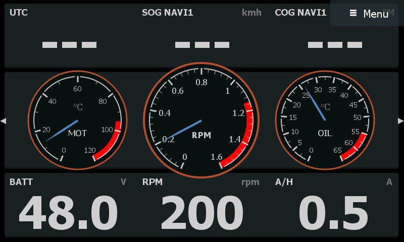
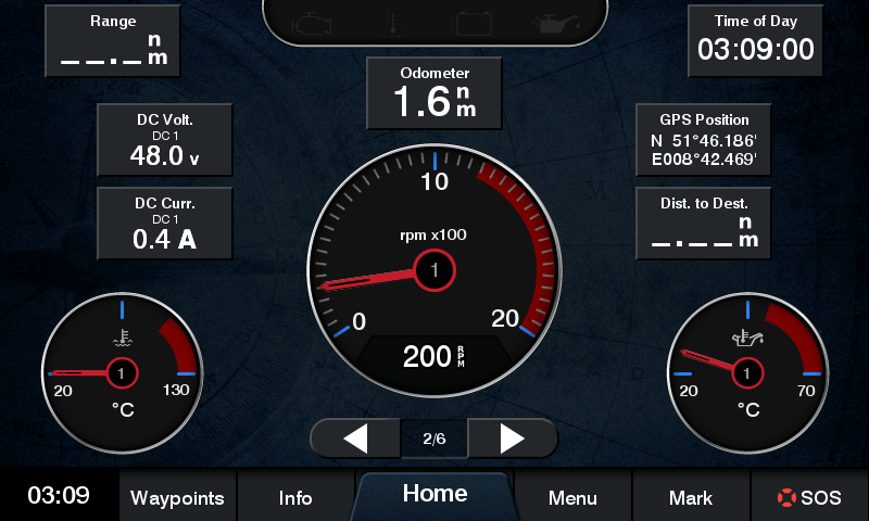
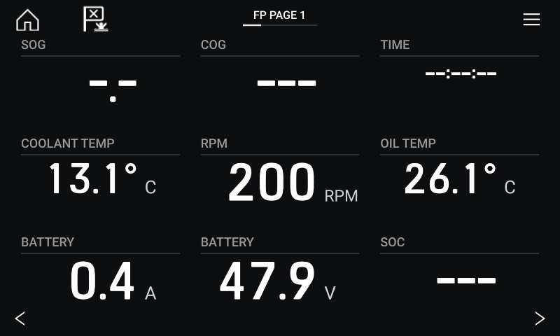
The data of the »Communication Interface Electric Drive – NMEA 2000®« can be displayed on current MFDs. Take a look at some examples: