
Application
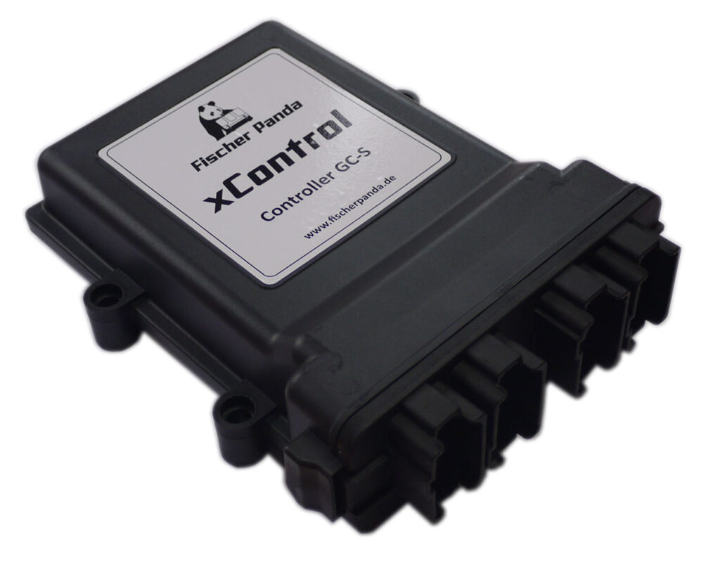
The »xControl Generator Control – Servo« (xControl GC-S) is a Generator Control for Fischer Panda asynchronous generators.
Product Description
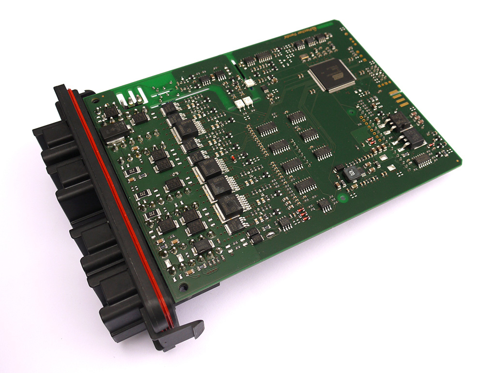
- As the main component of the xControl system, the Generator Control »xControl Generator Control – Servo« (xControl GC-S) takes all monitoring and control functions.
- During operation, the Generator Control »xControl GC-S« monitors critical operating conditions and switches off the generator in case of a fault.
- The »xControl GC-S« is suitable for 12 V and 24 V starting systems and is installed inside the generator capsule.
- The Generator Control communicates with the other system components via the »fpCAN«.
- Single-phase voltage measurement directly in the control unit.
- Single-phase current measurement via an external current sensor.
- For three-phase generators, the additional »fpControl Measurement Unit – MM-3« (fpControl MM-3) is required, which communicates with the control unit via the »fpCAN«.
Connectors
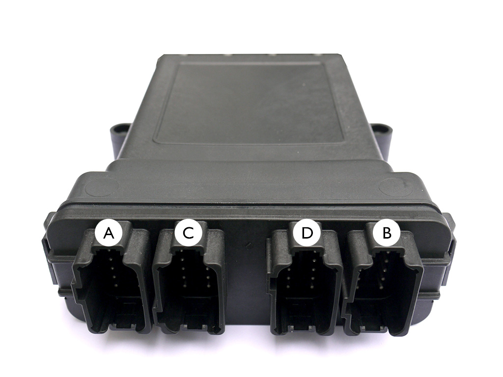
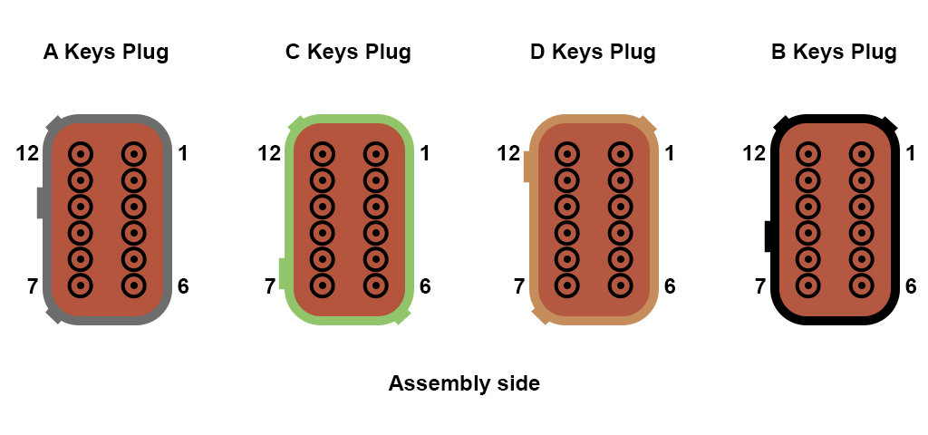
4 coded 12-pin sockets, from left to right: A coded, C coded, D coded and B coded.
Connector A
| Pin | Function |
| A1 | Digital Output (< 5 A @12-24 V DC), Water Pump |
| A2 | GND |
| A3 | Digital Output (< 5 A @12-24 V DC), Fuel Pump |
| A4 | GND |
| A5 | Digital Input, Emergency Stop |
| A6 | Digital Input, Emergency Stop |
| A7 | Automatic start |
| A8 | Wake-Up |
| A9 | Bus voltage + |
| A10 | Bus voltage GND |
| A11 | CAN High (Fischer Panda Bus) |
| A12 | CAN Low (Fischer Panda Bus) |
Connector C
| Pin | Function |
| C1 | Digital Output, Glowing |
| C2 | Digital Output, Glowing |
| C3 | Digital Output (< 1 A @12-24 V DC), Fuel Pump |
| C4 | GND |
| C5 | Servomotor, Voltage Supply (VCCS) (5 V, 1 A max.) |
| C6 | Servomotor, GNDS |
| C7 | Servomotor, PWM |
| C8 | Analog Input, Coolant Temperature (KTY11-6 / KTY81-210) |
| C9 | GND |
| C10 | ETR Hold (<4 A @12-24 V DC) |
| C11 | GND |
| C12 | ETR Pull (max. 60 A / 200 ms) |
Connector D
| Pin | Function |
| D1 | Supply voltage (12 V/24 V Automotive, Pre-fuse 40 A) |
| D2 | Supply voltage 12 V/24 V Automotive |
| D3 | Supply voltage 12 V/24 V Automotive |
| D4 | Supply voltage 12 V/24 V Automotive |
| D5 | GND |
| D6 | GND |
| D7 | Digital Input, Oil Pressure Switch |
| D8 | GND |
| D9 | Analog Input, Exhaust Temperature (KTY11-6 / KTY81-210) |
| D10 | GND |
| D11 | alternator / dynamo |
| D12 | Digital Output, Starter motor (20 A / 30 s) |
Connector B
| Pin | Function |
| B1 | Measurement voltage L1 |
| B2 | Measurement voltage N |
| B3 | unused |
| B4 | Current sensor (+5 V, 500 mA max.) |
| B5 | GND current sensor |
| B6 | AC/DC current sensor (Hall sensor 2,5 V +- 1 V) |
| B7 | Digital Output Boost Relay |
| B8 | GND |
| B9 | Analog Input, Winding Temperature (KTY11-6 / KTY81-210) |
| B10 | GND |
| B11 | Digital Output, Load Contactor (< 2 A @12-24 V DC) |
| B12 | GND |
Environmental specifications and physical data
| Operating temperature | -20 °C – +90 °C (max. peak 125 °C) |
| Storage temperature | -30 °C – +60 °C |
| Supply voltage | 12 V or 24 V, Automotive (12–13,5 V or 24–28 V) |
| Nominal current consumption | < 48 mA @12 V < 36 mA @24 V (in standby operation without consumer load) |
| Housing | Plastic housing from DEUTSCH Compagnie |
| Protection class | IP67 |
| Overall dimensions | 240 mm x 158 mm (including connectors) |
| Connector | 4 coded 12-pin connectors |
| Weight | 0,62 kg |
| FP part number | 0000292 |
| Printed circuit board | RE 1301 V5 |