
Application
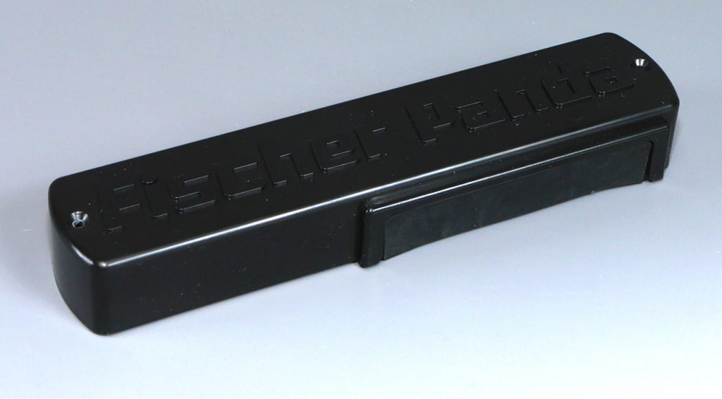
The »xControl Connection Board – Generator« (xControl CB-G) is for use at all Fischer Panda generators with the xControl system.
Product Description
- The »xControl Connection Board – Generator« (xControl CB-G) acts as an interface and establishes the connection between the system components within the generator capsule and the external components.
- It is located on the outside of the generator capsule and represents the external terminal block of the generator.
- The Control Panel »xControl Control Panel – Generator« (xControl CP-G) and the fuel pump are to this interface.
- Emergency stop switch, automatic start, powerline contactor and boost can optionally be connected via the »xControl CB-G«.
Connectors
All connections of the »xControl CB-G« are made with push-in spring cage connection terminals. Conductors with a maximum cross-section of 1.5 mm² can be connected here.
The »xControl CB-G« also has an RJ45 connection for the »fpCAN«.
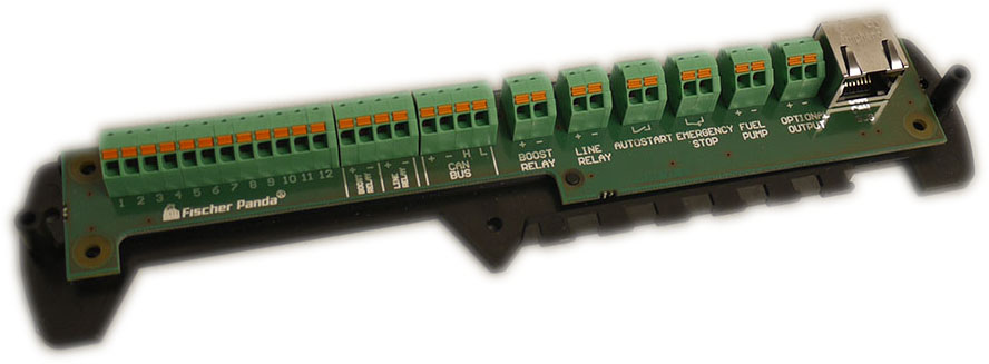
The order of the connectors in the table corresponds to the connectors in the figure from left to right.
| Connector | Assignment |
| X1 | xControl GC-S |
| X10 | xControl GC-S (Boost/Line Relay) |
| X6 | Alternative for the »fpCAN« |
| X8 | Boost Relay or DC power supply inverter |
| X9 | Powerline relay |
| X5 | Automatic start contact |
| X4 | Emergency stop |
| X3 | Digital output fuel pump (5 A) |
| X2 | Optional digital output water pump (PMS) or fan (PV) (5 A) |
| X7 | »fpCAN« or Control panel »xControl CP-G« |
Pin Assignments
Pin assignment of »X1« for »xControl GC-S«
12-pin Phoenix Contact socket.
| Pin | Label | Line |
| 1 | WP FAN | Digital output water pump / fan (+) |
| 2 | GND | GND of digital output water pump / fan |
| 3 | F-PUMP | Digital output fuel pump (+) |
| 4 | GND | GND of digital output fuel pump |
| 5 | ESTOP – | Emergency stop (-) |
| 6 | ESTOP + | Emergency stop (+) |
| 7 | AUTOSTART | Automatic start contact |
| 8 | WAKE | Wake-up line |
| 9 | U-BUS | Bus voltage (+) |
| 10 | GND | GND Bus voltage |
| 11 | CAN-H | CAN high |
| 12 | CAN-L | CAN low |
Pin assignment of »X10« for »xControl GC-S«
4-pin Phoenix Contact socket.
| Pin | Label | Line |
| 1 | BOOST | Digital output boost relay |
| 2 | UNIV 1 | Digital output multifunction output (5 A) |
| 3 | LINE | Digital output line relay |
| 4 | UNIV 2 | Digital output multifunction output (1 A) |
Pin assignment of »X6« for »fpCAN«
4-pin Phoenix Contact socket.
| Pin | Label | Line |
| 1 | CAN BUS + | Bus voltage (+) |
| 2 | CAN BUS – | Bus voltage (-) |
| 3 | CAN BUS H | CAN high |
| 4 | CAN BUS L | CAN low |
Pin assignment of »X8« for boost relay
2-pin Phoenix Contact socket.
| Pin | Label | Line |
| 1 | BOOSTRELAY (+) | Digital output boost relay (+) |
| 2 | BOOSTRELAY (-) | Digital output boost relay (-) |
Pin assignment of »X9« for powerline relay
2-pin Phoenix Contact socket.
| Pin | Label | Line |
| 1 | LINE RELAY (+) | Digital output powerline relay (+) |
| 2 | LINE RELAY (-) | Digital output powerline relay (-) |
Pin assignment of »X5« for automatic start contact
2-pin Phoenix Contact socket.
| Pin | Label | Line |
| 1 | AUTO START | Automatic start contact |
| 2 | Automatic start contact |
Pin assignment of »X4« for emergency stop
2-pin Phoenix Contact socket.
| Pin | Label | Line |
| 1 | EMERGENCY STOP | Emergency stop contact |
| 2 | Emergency stop contact |
Pin assignment of »X3« for digital output fuel pump (5 A)
2-pin Phoenix Contact socket.
| Pin | Label | Line |
| 1 | FUEL PUMP (+) | Digital output fuel pump (5 A) (+) |
| 2 | FUEL PUMP (-) | Digital output fuel pump (5 A) (-) |
Pin assignment of »X2« for optional digital output water pump (PMS) or fan (PV) (5 A)
2-pin Phoenix Contact socket.
| Pin | Label | Line |
| 1 | PMS / WP PV / FAN (+) | Digital output water pump (PMS) | or fan (PV) (5 A) (+) |
| 2 | PMS / WP PV / FAN (-) | Digital output water pump (PMS) | or fan (PV) (5 A) (-) |
Pin assignment of »X7« for »fpCAN« or Control panel »xControl CP-G«
RJ45 socket, Label »FP CAN BUS«.
| Pin | Line |
| 1 | CAN high |
| 2 | CAN low |
| 3 | GND |
| 4 | Wake up |
| 5 | Bus power |
| 6 | GND |
| 7 | GND |
| 8 | Bus power |
Environmental Specifications and Physical Data
| Storage temperature | -40 °C – +125 °C |
| Operating temperature | -20 °C – +100 °C |
| Supply voltage | no power supply |
| Rated current consumption | — |
| Housing | ABS plastic, FP part number 0000307 |
| Protection class | IP12 |
| Overall dimensions | 216,9 x 50,1 x 29,6 mm (L x W x H) |
| Weight | 0,13 kg |
| Printed circuit board | FP1301, FP part number 0000306 |
Accessories
fpCAN patch cable
Available in different length. With a data transfer rate of 250 kbps and up to 30 nodes, the maximum cable length is 40 meters.
| Length | Fischer Panda part number |
| 25 m | 0013474 |
| 15 m | 0004686 |
| 10 m | 0013473 |
| 6 m | 0013472 |
| 3 m | 0013471 |
| 1 m | 0013470 |
| 0,5 m | 0013468 |
| 0,2 m | 0013466 |