
Application
The »fpControl CAN Interface – SAE J1939« (fpControl CI-SAE J1939) is intended for use with asynchronous generators with xControl or fpControl control systems and for use with inverter generators with iControl2 control systems.
Product Description
- The »fpControl CAN Interface – SAE J1939« (fpControl CI-SAE J1939) manages the communication between the »fpCAN« and an external SAE J1939-CAN-BUS.
- The interface protects the internal »fpCAN« by filtering the data of the external CAN bus.
- Internal and external CAN bus are galvanically separated.
- The »fpControl CI SAE J1939« is supplied via the fpCAN.

Connectors

| Connector | Assignment |
| X106 | External fpCAN (label »FP CAN BUS 2«) |
| X107 | External fpCAN (label »FP CAN BUS 2«) |
| X105 | Alternative socket for the external fpCAN (label »USER CAN BUS«) |
| X103 | Supply voltage and internal fpCAN (FP CAN BUS 1) |
| X104 | Supply voltage and internal fpCAN (FP CAN BUS 1) |
 NOTE: Although the sockets X105 (label »USER CAN BUS«) and X106 / X107 (label »FP CAN BUS 2«) are labeled differently on the circuit board, their assignment is identical. The only difference is the alternative socket (5-pin Phoenix Contact socket / RJ45 socket). |
Pin Assignments
Pin assignment of »X106« and »X107« for the external fpCAN (FP CAN BUS 2)
External fpCAN, RJ45 socket.
Note: Bus termination is required if the »fpControl CI-SAE J1939« is the last module in the »fpCAN«.
| Pin | Line |
| 1 | CAN high |
| 2 | CAN low |
| 3 | GND |
| 4 | Wake up |
| 5 | Bus power |
| 6 | GND |
| 7 | GND |
| 8 | Bus power |
Pin assignment of »X105« for the alternative external fpCAN (USER CAN BUS)
5-pin Phoenix Contact socket.
| Pin | Label | Line |
| 1 | GND | GND |
| 2 | CAN-H | CAN high signal line |
| 3 | CAN-L | CAN low signal line |
| 4 | SHIELD | Shield |
| 5 | +U | Power source positive |
Pin assignment of »X103« and »X104« for the internal fpCAN (FP CAN BUS 1)
Internal fpCAN, RJ45 socket.
Note: Bus termination is required if the »fpControl CI-SAE J1939« is the last module in the »fpCAN«.
| Pin | Line |
| 1 | CAN high |
| 2 | CAN low |
| 3 | GND |
| 4 | Wake up |
| 5 | Bus power |
| 6 | GND |
| 7 | GND |
| 8 | Bus power |
Rotary Coding Switch
The rotary coding switch is used to add an offset to the start address for the address claiming process.
Default setting: Rotary coding switch in position »0«. No offset is added to the start address.
Alternative Setting: Rotary coding switch in a position not equal to »0«:
[start address] = [default start address] + [position of the rotary coding switch].
DIP Switch
The DIP switch of the »fpControl CI-SAE J1939« has no function and is intended for future use.
Environmental Specifications and Physical Data
Do not connect the Communication Interface to 48 V. This will damage the device. |
| Storage temperature | -30 °C – +60 °C |
| Operating temperature | -20 °C – +50 °C |
| Supply voltage | 12 V oder 24 V, Automotive (12–13,5 V oder 24–28 V) |
| Rated current consumption | < 32 mA @ 12 V < 17 mA @ 24 V |
| Housing | ABS Plastic (Bopla BOCUBE) |
| Protection class | IP30 |
| Overall dimensions | 151 x 80 x 60 mm (L x B x H) |
| Weight | 0,25 kg |
| FP part number | 0006107 |
| Printed circuit board | FP1409 |
Supported J1939 PGNs
A detailed documentation of the J1939 PGNs has to be bought from the SAE International website (SAE J1939-75 Generator Sets and Industrial Applications, https://www.sae.org).
ISO functions
| J1939 PGN Name | J1939 PGN # |
| ISO Acknowledgement | 59392 |
| ISO Request | 59904 |
| ISO Transport Protocol, Data Transfer | 60160 |
| ISO Transport Protocol, Conn. Management | 60416 |
| ISO Address Claim | 60928 |
SAE J1939 functions
| J1939 PGN Name | J1939 PGN # |
| PROPA00, Remote Procedure Request | 61184 |
| EEC1, Electronic Engine Controller #1 | 61444 |
| GTACPP, Generator Total AC Percent Power | 64911 |
| UPCACR, Utility Phase C AC Reactive Power | 65006 |
| UPCACP, Utility Phase C AC Power | 65007 |
| UPCAC, Utility Phase C Basic AC Quantities | 65008 |
| UPBACRP, Utility Phase B AC Reactive Power | 65009 |
| UPBACP, Utility Phase B AC Power | 65010 |
| UPBAC, Utility Phase B Basic AC Quantities | 65011 |
| UPAACR, Utility Phase A AC Reactive Power | 65012 |
| UPAACP, Utility Phase A AC Power | 65013 |
| UPAAC, Utility Phase A Basic AC Quantities | 65014 |
| GPCACR, Generator Phase C AC Reactive Power | 65019 |
| GPCACP, Generator Phase C AC Power | 65020 |
| GPCAC, Generator Phase C Basic AC Quantities | 65021 |
| GPBACRP, Generator Phase B AC Reactive Power | 65022 |
| GPBACP, Generator Phase B AC Power | 65023 |
| GPBAC, Generator Phase B Basic AC Quantities | 65024 |
| GPAACR, Generator Phase A AC Reactive Power | 65025 |
| GPAACP, Generator Phase A AC Power | 65026 |
| GPAAC, Generator Phase A Basic AC Quantities | 65027 |
| GAAC, Generator Average Basic AC Quantities | 65030 |
| HOURS, Engine Hours | 65253 |
| ET1, Electronic Temperatures #1 | 65262 |
| EFLP1, Engine Fluid Level / Pressure #1 | 65263 |
| DD, Dash Display | 65276 |
| PROPB00, Response for PROPA00 RPC request | 65280 |
| PROPB01, System information | 65281 |
| PROPB03, RPM | 65283 |
| PROPB05, Extended parameters | 65285 |
| PROPB0A, Inverter Errors, Warnings, Servo position request | 65290 |
| PROPB0B, Temperatures Inverter | 65291 |
| PROPB14, AGT 1 (Generator DC Output) | 65300 |
| PROPB15, AGT 2 (DC Load) | 65301 |
| PROPB16, AGT 3 (temperatures) | 65302 |
| PROPB17, AGT 4 (AC voltage, frequency and current) / Hybrid Charger (HC) | 65303 |
| PROPB18, AGT 5 (Battery charge) | 65304 |
| PROPB19, AGT 6 (Battery charger control value and limiter) | 65305 |
| PROPB1A, AGT 7 (Charger output mode and value) | 65306 |
| PROPB1B, AGT 8 (Power Control) | 65307 |
| PROPB1D, AGT 9 (Hybrid Charger) | 65309 |
Supported J1939 SPNs
| SPN | Content | PGN Reference |
| 96 | Fuel Level 1 | 65276 |
| 100 | Engine Oil Pressure | 65263 |
| 110 | Engine Coolant Temperature | 65262 |
| 174 | Engine Fuel Temperature | 65262 |
| 175 | Engine Oil Temperature | 65262 |
| 247 | Operating Hours | 65253 |
| 190 | Engine Speed | 61444 |
| 513 | Engine Load | 61444 |
| 2436 | Generator Average AC Frequency | 65030 |
| 2437 | Generator Phase A AC Frequency | 65027 |
| 2438 | Generator Phase B AC Frequency | 65024 |
| 2439 | Generator Phase C AC Frequency | 65021 |
| 2440 | Generator Average Line-Line AC RMS Voltage | 65030 |
| 2441 | Generator Phase AB Line-Line AC RMS Voltage | 65027 |
| 2442 | Generator Phase BC Line-Line AC RMS Voltage | 65024 |
| 2443 | Generator Phase CA Line-Line AC RMS Voltage | 65021 |
| 2444 | Generator Average Line-Neutral AC RMS Voltage | 65030 |
| 2445 | Generator Phase A Line-Neutral AC RMS Voltage | 65027 |
| 2446 | Generator Phase B Line-Neutral AC RMS Voltage | 65024 |
| 2447 | Generator Phase C Line-Neutral AC RMS Voltage | 65021 |
| 2448 | Generator Average AC RMS Current | 65030 |
| 2449 | Generator Phase A AC RMS Current | 65027 |
| 2450 | Generator Phase B AC RMS Current | 65024 |
| 2451 | Generator Phase C AC RMS Current | 65021 |
| 2453 | Generator Phase A Real Power | 65026 |
| 2454 | Generator Phase B Real Power | 65023 |
| 2455 | Generator Phase C Real Power | 65020 |
| 2457 | Generator Phase A Reactive Power | 65025 |
| 2458 | Generator Phase B Reactive Power | 65022 |
| 2459 | Generator Phase C Reactive Power | 65019 |
| 2461 | Generator Phase A Apparent Power | 65026 |
| 2462 | Generator Phase B Apparent Power | 65023 |
| 2463 | Generator Phase C Apparent Power | 65020 |
| 2465 | Generator Phase A Power Factor | 65025 |
| 2466 | Generator Phase B Power Factor | 65022 |
| 2467 | Generator Phase C Power Factor | 65019 |
| 2471 | Utility Phase A AC Frequency | 65014 |
| 2472 | Utility Phase B AC Frequency | 65011 |
| 2473 | Utility Phase C AC Frequency | 65008 |
| 2475 | Utility Phase AB Line-Line AC RMS Voltage | 65014 |
| 2476 | Utility Phase BC Line-Line AC RMS Voltage | 65011 |
| 2477 | Utility Phase CA Line-Line AC RMS Voltage | 65008 |
| 2479 | Utility Phase A Line-Neutral AC RMS Voltage | 65014 |
| 2480 | Utility Phase B Line-Neutral AC RMS Voltage | 65011 |
| 2481 | Utility Phase C Line-Neutral AC RMS Voltage | 65008 |
| 2483 | Utility Phase A AC RMS Current | 65014 |
| 2484 | Utility Phase B AC RMS Current | 65011 |
| 2485 | Utility Phase C AC RMS Current | 65008 |
| 2487 | Utility Phase A Real Power | 65013 |
| 2488 | Utility Phase B Real Power | 65010 |
| 2489 | Utility Phase C Real Power | 65007 |
| 2491 | Utility Phase A Reactive Power | 65012 |
| 2492 | Utility Phase B Reactive Power | 65009 |
| 2493 | Utility Phase C Reactive Power | 65006 |
| 2495 | Utility Phase A Apparent Power | 65013 |
| 2496 | Utility Phase B Apparent Power | 65010 |
| 2497 | Utility Phase C Apparent Power | 65007 |
| 2499 | Utility Phase A Power Factor | 65012 |
| 2500 | Utility Phase B Power Factor | 65009 |
| 2501 | Utility Phase C Power Factor | 65006 |
| 2519 | Generator Phase A Power Factor Lagging | 65025 |
| 2521 | Generator Phase C Power Factor Lagging | 65019 |
| 2522 | Utility Overall Power Factor Lagging | 65021 |
| 2523 | Utility Phase A Power Factor Lagging | 65012 |
| 2524 | Utility Phase B Power Factor Lagging | 65009 |
| 2525 | Utility Phase C Power Factor Lagging | 65006 |
| 3590 | Generator Total Percent kW | 64911 |
| 3591 | Generator Total Percent kVA | 64911 |
| 3592 | Generator Total Percent kVAr | 64911 |
| 520192 | System State | 65281 |
| 520193 | Delay until next state | 65281 |
| 520195 | Error Code | 65281 |
| 520200 | System Battery Voltage | 65281 |
| 520201 | Cyclic recurring unacknowledged warnings | 65281 |
| 520202 | Cyclic recurring all active warnings | 65281 |
| 520203 | Special configuration bits | 65281 |
| 520204 | Temperature Winding | 65285 |
| 520205 | Temperature Exhaust | 65285 |
| 520206 | Temperature MCU | 65285 |
| 520207 | AGT Gen-Out DC Voltage | 65300 |
| 520208 | AGT Gen-Out DC Current | 65300 |
| 520209 | AGT Gen-Out DC Power | 65300 |
| 520210 | AGT Load DC Voltage | 65301 |
| 520211 | AGT Load DC Current | 65301 |
| 520212 | AGT Load DC Power | 65301 |
| 520217 | Inverter Temperature L1 | 65291 |
| 520224 | Inverter Temperature L2 | 65291 |
| 520225 | Inverter Temperature L3 | 65291 |
| 520226 | AGT Temperature Heatsink | 65302 |
| 520227 | AGT Temperature Rail+ | 65302 |
| 520228 | AGT Temperature Rail- | 65302 |
| 520229 | AGT Temperature Electronic (MCU) | 65302 |
| 520230 | Engine Speed | 65283 |
| 520231 | AGT AC Frequency | 65303 |
| 520232 | Error (fpCAN Event Code) | 65290 |
| 520233 | Warning (fpCAN Event Code) | 65290 |
| 520234 | Servo position request (corresponds to the load level) | 65290 |
| 520235 | Inverter Temperature DC Link | 65291 |
| 520269 | AGT Battery Charge | 65304 |
| 520270 | AGT flags control variable, type of limiter, limiter active/not active | 65305 |
| 520271 | AGT Battery Capacity | 65305 |
| 520272 | AGT Battery Voltage | 65305 |
| 520273 | AGT Battery Current | 65305 |
| 520274 | AGT Charger Output Mode | 65306 |
| 520275 | AGT Charger Output Value | 65306 |
| 520276 | AGT Charger State | 65306 |
| 520277 | AGT AC Voltage | 65303 |
| 520278 | AGT AC Current | 65303 |
| 520280 | AGT AC Power | 65303 |
| 520294 | HYBR Error Bit Field (for future use) | 65309 |
| 520295 | HYBR States (for future use) | 65309 |
| 520296 | HYBR Servo Control Mode | 65309 |
| 520297 | HYBR Servo Position Request | 65309 |
| 520298 | HYBR Precharge – DC Bus Voltage | 65309 |
The SPNs from 520192 are proprietary. A detailed description is available on request. |
PGNs supported by AGT Generators
| J1939 PGN Name | J1939 PGN # |
| PROPA00, Remote Procedure Request | 61184 |
| EEC1, Electronic Engine Controller #1 | 61444 |
| HOURS, Engine Hours | 65253 |
| ET1, Electronic Temperatures #1 | 65262 |
| EFLP1, Engine Fluid Level / Pressure #1 | 65263 |
| PROPB00, Response for PROPA00 RPC request | 65280 |
| PROPB01, System information | 65281 |
| PROPB03, RPM | 65283 |
| PROPB05, Extended parameters | 65285 |
| PROPB14, AGT 1 (Generator DC Output) | 65300 |
| PROPB15, AGT 2 (DC Load) | 65301 |
| PROPB16, AGT 3 (temperatures) | 65302 |
| PROPB17, AGT 4 (AC voltage, frequency and current) / Hybrid Charger (HC) | 65303 |
| * PROPB18, AGT 5 (Battery charge) | 65304 |
| ** PROPB19, AGT 6 (Battery charger control value and limiter) | 65305 |
| PROPB1A, AGT 7 (Charger output mode and value) | 65306 |
| ** PROPB1B, AGT 8 (Power Control) | 65307 |
| *** PROPB1D, AGT 9 (Hybrid Charger) | 65309 |
* The cyclic transmission of the PGN 65304 can be deactivated / activated. ** This message must be sent cyclically to the AGT. If this message is not received cyclically by the AGT, it goes to idle for safety reasons (timeout: 250 ms). *** Only Hybrid Charger Generators. |
Accessories
fpCAN patch cable
Available in different lengths:
| Length | Fischer Panda part number |
| 25 m | 0013474 |
| 15 m | 0004686 |
| 10 m | 0013473 |
| 6 m | 0013472 |
| 3 m | 0013471 |
| 1 m | 0013470 |
| 0,5 m | 0013468 |
| 0,2 m | 0013466 |
Terminating resistor
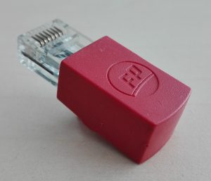
The ends of the »fpCAN« network must be terminated with a 120 ohm resistor.
fpCAN terminating resistor 120 Ohm with RJ45 connector, red RAL 3000 with FP logo. Fischer Panda article number 0003022.
Adapter cable iControl2
Fischer Panda article number 0008899.
Glossary
- S
- SAE J1939 – Standard for a network protocol that describes the communication on a CAN bus for commercial vehicles.
- SPN – Abbr. Suspect Parameter Number. The parameters of a PGN are called SPNs.
- P
- PGN – Abbr. Parameter Group Number. In the SAE J1939 standard a PGN groups several parameters that belong to the same topic and have the same transmission rate. For example, AC voltage, AC frequency and AC current of one phase are grouped in one PGN.