
Application
The »iControl3 Control Panel« is intended for use on generators with »iControl 2.5« and »iControl3« system. It is the user interface of the control system and is used to operate and display system data.
 The »iControl3 Control Panel« is pin-compatible with the previous »iControl 2 Control Panel« and has the same dimensions. Therefore the »iControl3 Control Panel« can be used as a replacement panel on all generator types with iControl 2 generator control. |
Product Description
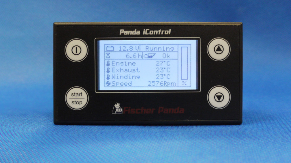
- Release: P: 3.01.000 or higher, P: Panel | 3 Hardware release | 01 Software release | 000 Revision
- Fischer Panda part number: 0034806
- The controls are the same as the iControl 2 panel.
- The known display pages of the iControl2 panel remain unchanged.
- The assignment of the socket for the panel connection cable (see number 1 in »Connectors and switches«) is pin-compatible with the iControl2 panel.
- The automatic start contact is on a separate connection socket (see number 2 in »Connectors and switches«).
- The display pages for error messages have been given a new layout.
Connectors and Switches
There are 6 connectors and a double DIP switch on the backside of the »iControl3 Control Panel«.
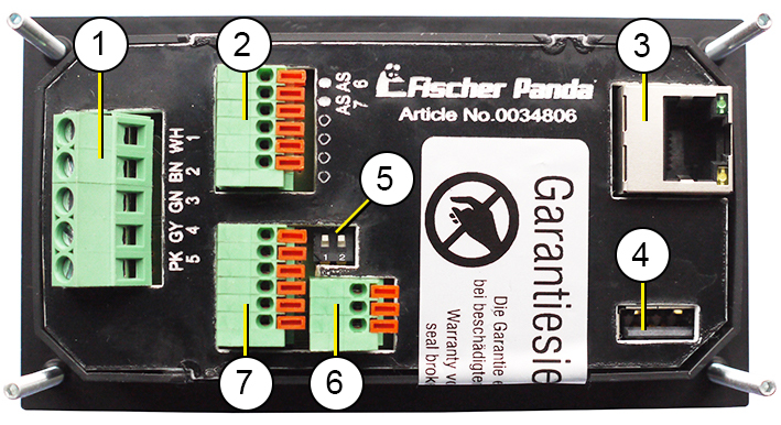
| 1 | 5-pin Phoenix socket for panel connecting cable |
| 2 | Automatik start (pins AS 6 and AS 7) |
| 3 | Network, for example Ethernet (For future use. NOTE: This socket must not be used. The electronics can be damaged.) |
| 4 | USB (For future use. NOTE: This socket must not be used. The electronics can be damaged.) |
| 5 | Double DIP switch, switching on/off the terminating resistors for CAN bus 1 and CAN bus 2 |
| 6 | Fischer Panda CAN Bus 2, CAN interface, j1939 based »fpCAN« (for future use) |
| 7 | 3 universal outputs (For future use. NOTE: These sockets must not be used. The electronics can be damaged.) |
Terminal assignment of the 5-pin Phoenix socket
See number 1 in »Connectors and switches«.
| 1 | UBUS | white (WH) | Bus supply voltage |
| 2 | GND | brown (BN) | Bus ground |
| 3 | RZL | green (GN) | Exciter wire |
| 4 | CAN Low | grey (GY) | Fischer Panda CAN bus 1 |
| 5 | CAN High | pink (PK) | Fischer Panda CAN bus 1 |
Environmental Specifications and Physical Data
| Supply voltage | 12 V-24 V (12 V or 24 V automotive) |
| Current consumption, off | 0 mA |
| Current consumption, stand-by – backlight brightness 90 % | 60 mA |
| Current consumption, stand-by – backlight brightness 40 % | 50 mA |
| Current consumption, stand-by – backlight brightness 0 % | 40 mA |
| Operating temperature | -20 °C to +50 °C |
| Storage temperature | -30 °C to +60 °C |
| Housing | ABS plastic |
| Protection class | IP04 |
| Overall dimensions | 120 x 65 x35 mm (L x W x H), Cutout: 109,2 x 54,5 mm |
| FP part number | 0034806 |
| Printed circuit board | FP2105 |
Master and Slave Panels
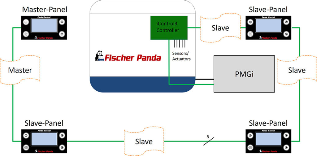
With the »iControl3 Control Panel« it is possible to operate up to four panels on one iGenerator (one master panel and three slave panels).
On the master panel the terminating resistor for the CAN bus must be switched on. The terminating resistor of the slave panel must be switched off. To do this there is a double DIP switch on the backside of the »iControl3 Control Panel« (see »Function of the double DIP Switch«).
In an iControl system with master and slave panels, the master panel must always be the last panel in the row so that the terminating resistor is at the end of the CAN bus. Slave panels must be connected between the »iControl3 Generator Control« and the master panel.
Note: When operating an »iControl3 Control Panel« as a replacement panel in an iControl2 system, the network address must be considered: All iControl3 panels have the default network address “1”. This address can be changed in the set up menu. Possible addresses are 1, 2, 3 and 4. |
Note: The automatic start function can be activated/deactivated on each panel in the bus. The automatic start contact may only be connected to one panel in the bus. |
Function of the Double DIP Switch
The terminating resistors for CAN bus 1 and CAN bus 2 are switched on and off with the double DIP switch (see number 5 in »Connectors and switches«).
| Switch | Function | Switch position |
| 1 | Terminating resistor for CAN bus 1 On/Off | top – terminating resistor “ON”, down – terminating resistor “OFF” |
| 2 | Terminating resistor for CAN bus 2 On/Off | top – terminating resistor “ON”, down – terminating resistor “OFF” |