
Application
The »iControl4 Control Panel« provides the user interface for generators equipped with the iControl4 control system. It allows the operator to control the generator, monitor system functions, and view operating data.
Product Description
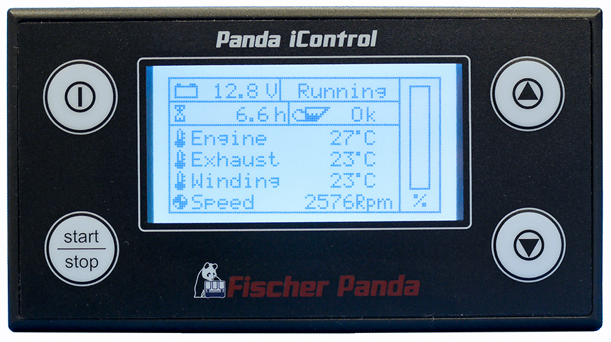
- Fischer Panda part number: 0039433
- Automatic start contact to start and stop the generator in addition to the start / stop button.
- Operating temperature range from -20 °C to +50 °C.
- Display resolution: 128 x 64 pixels.
- Up to four panels can be operated in an iControl4 control system.
- Terminating resistors are swichable with a double DIP switch.
Controls
| Button Symbol | Function |
 | on / off |
 | up |
 | down |
 | start / stop |
Connectors and Switches
There are 7 connectors and one double DIP switch on the backside of the »iControl4 Control Panel«.
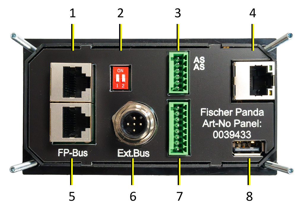
| # | Assignment |
| 1 | RJ45 connector for supply voltage and CAN Bus |
| 2 | Double DIP switch for switching on/off the terminating resistors for CAN Bus 1 and CAN Bus 2 |
| 3 | Inputs (Autostart, Universal Input 1 and 2) |
| 4 | RJ45 (For future use. NOTE: This socket must not be used. The electronics can be damaged.) |
| 5 | RJ45 connector for supply voltage and CAN Bus |
| 6 | 5-pin male NMEA 2000® connector (M12) |
| 7 | Universal Outputs 1 to 4 (max. 100 mA) |
| 8 | USB (For future use. NOTE: This socket must not be used. The electronics can be damaged.) |
Pin Assignments
Pin assignment of the RJ45 connectors for supply voltage and CAN Bus
See number 1 and 5 in »Connectors and switches«.
| Pin | Line |
| 1 | GND |
| 2 | Bus Power +12 V |
| 3 | GND |
| 4 | Wake-Up (Exciter Wire) |
| 5 | reserved |
| 6 | Bus Power +12 V |
| 7 | CAN High |
| 8 | CAN Low |
Pin assignment of the connector for the Inputs (Autostart, Input 1, Input 2)
See number 3 in »Connectors and switches«.
| Pin | Line |
| 1 | Autostart |
| 2 | GND |
| 3 | Input 1 |
| 4 | GND |
| 5 | Input 2 |
| 6 | GND |
Pin assignment of the connector for the Universal Outputs
See number 7 in »Connectors and switches«.
| Pin | Line |
| 1 | +12 V |
| 2 | Universal Output 1 |
| 3 | +12 V |
| 4 | Universal Output 2 |
| 5 | +12 V |
| 6 | Universal Output 3 |
| 7 | +12 V |
| 8 | Universal Output 4 |
Pin assignment of the 5-pin male NMEA 2000® connector (M12)
See number 6 in »Connectors and switches«.
| Pin | Line |
| 1 | Shield |
| 2 | NET-S | Power source positive (unused) |
| 3 | NET-C | Power source common |
| 4 | NET-H | CAN High signal line |
| 5 | NET-L | CAN Low signal line |

Function of the Double DIP Switch
The terminating resistors for CAN bus 1 and CAN bus 2 are switched on and off with the double DIP switch (see number 2 in »Connectors and switches«).
| Switch | Function | Switch position |
| 1 | Terminating resistor for CAN bus 1 On/Off | top – terminating resistor “ON”, down – terminating resistor “OFF” |
| 2 | Terminating resistor for CAN bus 2 On/Off | top – terminating resistor “ON”, down – terminating resistor “OFF” |
Environmental Specifications and Physical Data
| Supply voltage | 12 V-24 V (12 V or 24 V automotive) |
| Current consumption, off | 0 mA |
| Current consumption, stand-by – backlight brightness 90 % | 60 mA |
| Current consumption, stand-by – backlight brightness 40 % | 50 mA |
| Current consumption, stand-by – backlight brightness 0 % | 40 mA |
| Operating temperature | -20 °C to +50 °C |
| Storage temperature | -30 °C to +60 °C |
| Housing | ABS plastic |
| Protection class | IP04 |
| Overall dimensions | 120 x 65 x 35 mm (L x W x H), Cutout: 109,2 x 54,5 mm |
| FP part number | 0039433 |
| Printed circuit board | FP2105 |
Multiple Panels
With the »iControl4 Control Panel« it is possible to operate up to four panels in an iControl4 control system. In this case the last panel in the bus must always be terminated. The terminating resistor of the other panels must be switched off.
For switching the terminating resistor there is a double DIP switch on the backside of the »iControl4 Control Panel« (see »Function of the double DIP Switch«).
 Note: The automatic start function can be activated/deactivated on each panel in the bus. The automatic start contact may only be connected to the panel with address 1. |